Finned Aluminium Rotor Housing — 38 Fins, 0.9 mm Walls
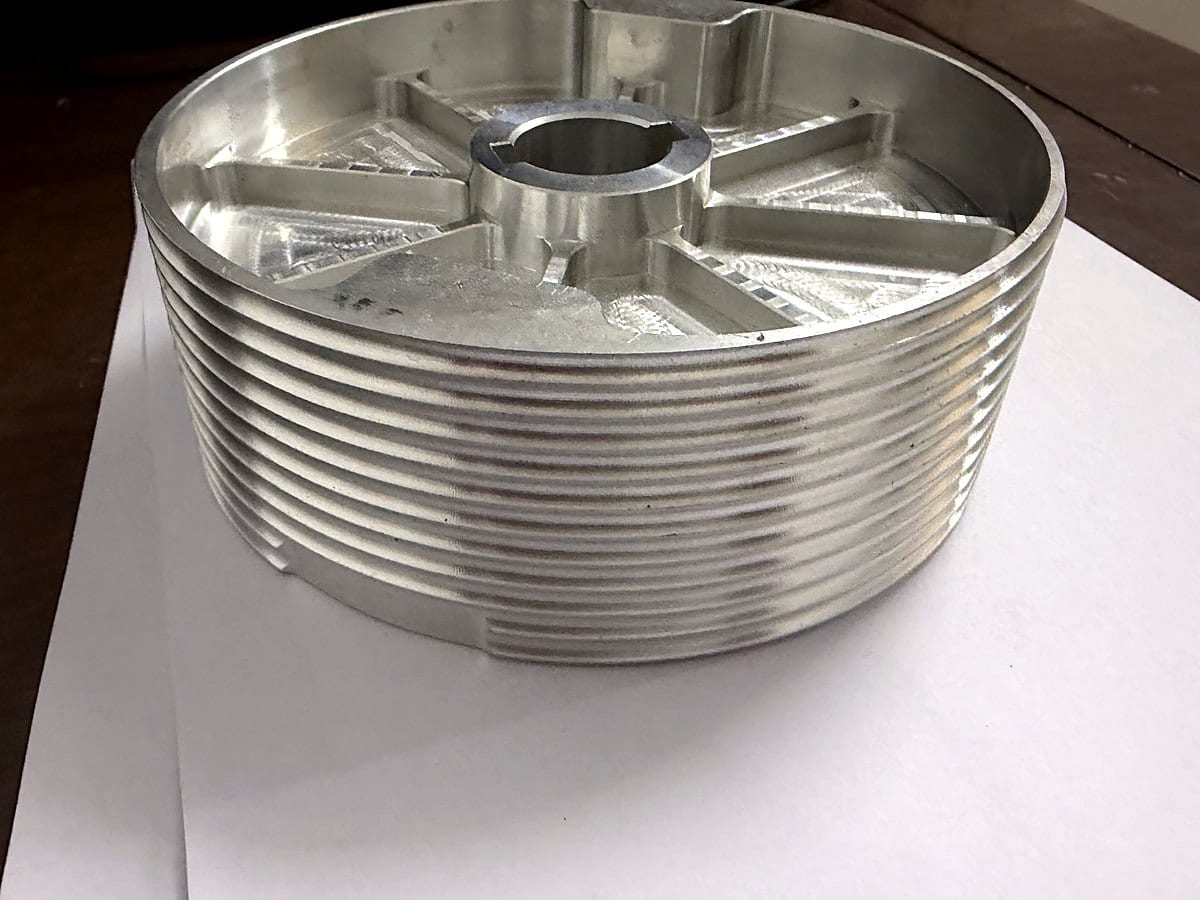
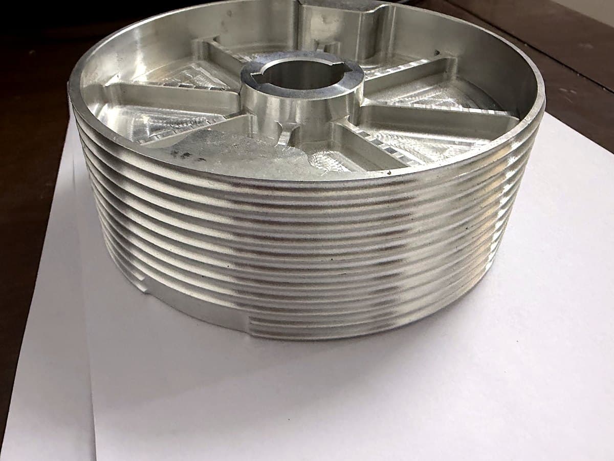
A finned rotor housing with 38 turned fins and six internal ribs, machined from 6061-T6 billet with 0.9 mm fin walls held to ±0.05 mm across the full 160 mm diameter.
Part specification
- Industry
- Industrial Machinery
- Process
- CNC Turning + Milling
- Material
- Aluminium 6061-T6
- Tolerance
- ±0.05 mm
- Finish
- Bead blasted, clear anodised
- Quantity
- 250 / release
- Lead time
- 14 working days
Customer details withheld under NDA.
Challenge
The customer's previous supplier could not hold fin thickness consistently: fins near the outer diameter came out 0.15 mm thicker than those near the hub, and roughly one part in five showed chatter marks that failed the cosmetic specification. Thermal performance depends on fin pitch, so the variation was a functional problem, not just an appearance one.
Solution
We reversed the process order — turning the fin profile first while the billet was still rigid, then milling the internal rib pocket from the back with the part supported on a purpose-built vacuum fixture. Fins were cut with a ground form tool at constant surface speed and a light final pass, and the job was stress-relieved between roughing and finishing to stop the hub pulling as material came out.
Result
Fin thickness now holds ±0.05 mm from hub to rim, chatter has been eliminated, and the scrap rate dropped from 19 % to under 1 %. Cycle time fell 22 % against the original process despite adding the stress-relief step. The part has been in repeat production for eleven releases.
Why this part was difficult
Thin fins on a rotating component are a textbook thin-wall problem with an added complication: the fins must be dimensionally consistent because fin pitch determines airflow, and the part must be balanced because it rotates.
Machining fins from the outside inwards progressively removes the material that supports the next cut. By the time the tool reaches the last fin, the section is thin, unsupported and free to deflect.
Process sequence
- Rough turn the outer profile, leaving 1 mm on all surfaces
- Stress relieve (4 hours, controlled cool)
- Finish turn fins with a ground form tool, constant surface speed, 0.15 mm depth of cut per pass
- Transfer to vacuum fixture, mill internal rib pocket and hub bore
- Deburr, dynamic balance check, bead blast, clear anodise
Inspection
Fin thickness is measured at four angular positions on every tenth part with a calibrated blade micrometer, and the first article was verified on the CMM with a scanning routine across all 38 fins. Balance is checked against the customer's G2.5 requirement.
Send us your drawing today
STEP, IGES, X_T, DWG, DXF, PDF or STL. Every file is treated as confidential and covered by NDA on request.