Hardened Gear Set — Ground After Heat Treatment
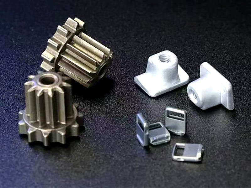
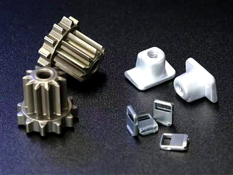
A set of spur gears and drive components, machined in the annealed condition, case-hardened to 60 HRC and finish-ground to restore geometry lost to heat-treatment distortion.
Part specification
- Industry
- Industrial Machinery
- Process
- Precision Grinding
- Material
- Steel 4140 / case-hardened
- Tolerance
- ±0.002 mm
- Finish
- Ground, Ra 0.2 µm on flanks
- Quantity
- 400 / year
- Lead time
- 25 working days
Customer details withheld under NDA.
Challenge
The previous process hardened the gears after finish machining and accepted whatever distortion resulted. Noise levels varied between batches and roughly 12 % of parts fell outside the tooth profile tolerance after hardening.
Solution
The routing was changed to machine in the annealed condition with a grinding allowance on the bore, faces and tooth flanks, then case-harden, then finish-grind. Bore and faces are ground on a cylindrical grinder; tooth flanks are profile-ground against the theoretical involute.
Result
Tooth profile now holds DIN quality 7 consistently. The out-of-tolerance rate after hardening fell from 12 % to zero, because the geometry is created after the distortion rather than before it. Measured noise at rated speed dropped by 4 dB(A).
Hardening moves steel
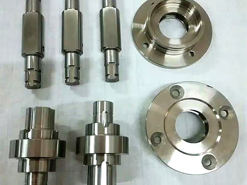
Case hardening introduces a volume change in the carburised layer and a thermal gradient through the section. The result is distortion — typically 0.05 to 0.2 mm on a gear of this size, which is an order of magnitude larger than the tooth profile tolerance.
You cannot prevent it. You can only decide whether to create the final geometry before or after it happens.
Revised routing
- Turn and hob in the annealed condition, leaving 0.25 mm grinding allowance on bore, faces and flanks
- Case harden to 60 HRC, case depth 0.8 – 1.2 mm
- Temper and stress relieve
- Grind bore and reference face on a cylindrical grinder
- Profile grind tooth flanks from the ground bore as datum
- Final inspection — profile, lead, pitch and runout
Send us your drawing today
STEP, IGES, X_T, DWG, DXF, PDF or STL. Every file is treated as confidential and covered by NDA on request.